Saving a router
2021-03-25 📖 8 min
One day, my Asus RT-N12-D1 router died. An update did go terribly wrong, and the software got messed up to the point where the LEDs were turning on, and stayed that way. The router did not show up on the network, it was time for recovery.
Introduction
There are a lot of resources about hacking into a router, usually with the aim of installing OpenWRT or DD-WRT. Some are quite old, leading to dead links, or do not apply for your specific situation. However, checking the forums and wikis of the two projects mentioned earlier is a mandatory step.
One good source of information that needs to be read is the so-called Peacock thread which compiles a ton of interesting information, which can be useful.
Tentative 1: CFE and RS232
When the router starts, a little piece of code is executed first, before actually starting the main operating system. On computers, it's known as the BIOS or UEFI. The bootloader, on this router, is the Common Firmware Environment. It's not required for it to be there at all, but it provides few useful functions. One of which being able to flash the internal memory with a new firmware image for update or recovery. To do so, the instructions need to be sent over a RS232 (serial) connection.
Computer side
The RS232 link is pretty simple, especially if we consider the absolute minimum of wires required:
- The ground (GND) reference, so the two devices know what is the zero volts level: voltages are relative to one another.
- One data line to carry the data sent from the transmit (TX) wire of one device to the receiving (RX) wire of the other device.
- Another data line, going the other way round.
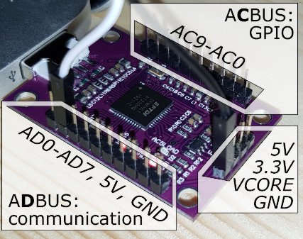
Computers used to come with hardware serial ports, but they disappeared in favour of the Universal Serial Bus (USB) which has many technical benefits. However, it is possible to USB adapters to talk RS232 easily. I have such an adapter in the form of a small board known online as FT232H CJMCU. It's a very versatile board as it features a FTDI FT232H chip, that can handle multiple communication protocols.
In this recovery attempt, first want to listen to what the router says, therefore the connection only requires to connect the RX (receive) pin of the board to the TX (transmit) pin from the router. With the board I have, it only requires connecting the AD1 pin for the communication (thanks Adafruit for the easy to read documentation for a similar board!), along with the usual GND line (otherwise the computer and the router may not have the same value for the zero volts level: voltages are relative to one another).
Router side
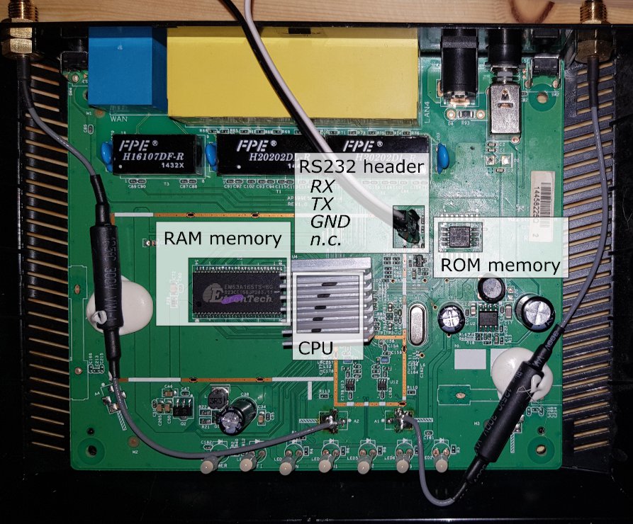
Searching online, I quickly find where is the serial port on the board of the device. I solder the header on the pins using an iron that is not powerful enough to properly heat up the ground (GND) line. Indeed, the GND signal is usually filling all the space not used for electrical lines, and therefore it becomes really hard to warm up as it radiates the heat away very efficiently (thus making soldering difficult).
Talking to each other
Once connected to the computer, I open the serial connection to see any possible activity. The ultimate goal is to send the Ctrl+C signal on the serial link as soon as the router is powered on to enter the CFE utility and tell it to accept a new firmware image. However, we first want to listen to what is said, so there is nothing to send at first. Not knowing which is the correct speed, I tried several standard ones (9600, 19200, 38400, 57600 and 115200), with the example of 19200 bauds in the example below:
$ minicom --device /dev/tty.usbserial-1420 --baudrate 19200

Welcome to minicom 2.8

OPTIONS:
Compiled on Jan  4 2021, 00:04:03.
Port /dev/tty.usbserial-1420, 16:55:43

Press Meta-Z for help on special keys

??
Every time, I got nothing meaningful from the router: the CFE bootloader is dead.
Tentative 2: flashing the chip
The situation is quite critical as nothing works at all. There is no magic software command to save the router now. The only hope is to reprogram the memory chip directly. One possibility is to reprogram it completely, with the bootloader and the firmware. The other possibility is to only flash the CFE bootloader and use that for then flashing the firmware. This is what I will do as reprogramming the memory is significantly slower than first programming the bootloader, and the using it to flash the firmware image.
The memory
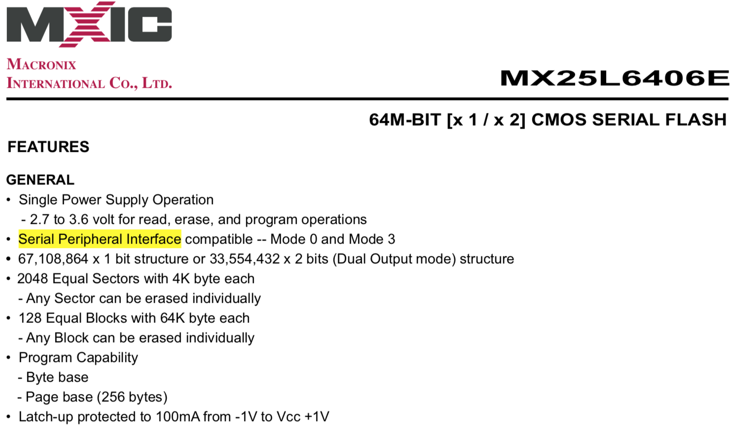
Checking online on the OpenWRT wiki, I find that the memory chip used is the MX25L6406E from Macronix. From the technical datasheet, we learn that this chip can be programmed using an Serial Peripheral Interface (SPI) connection.
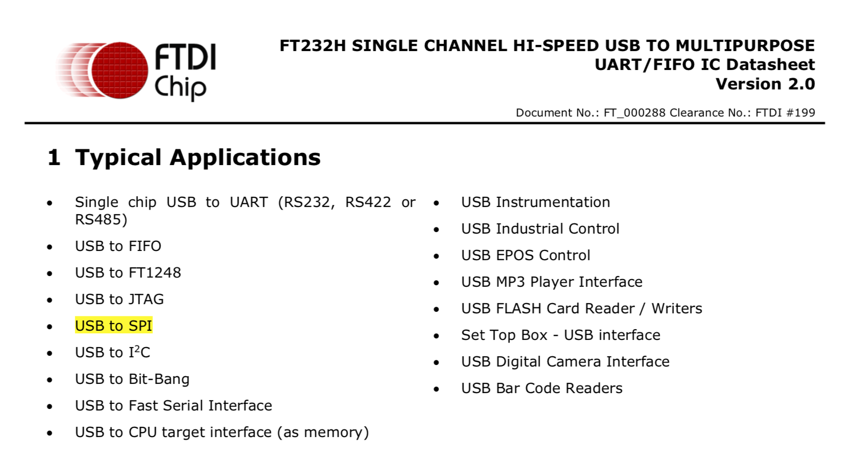
Now we know it talks SPI, we need an interface on the computer that also talks SPI. And, once again, I will be using the board with the FTDI FT232H chip already used previously. Indeed, it can also talk SPI:
Connecting everything together
We now know what hardware to use, we need to check the pinouts of the different items to learn how to connect everything. First, for the memory chip, we will be using a clip to get easy access to the pins. Indeed, it uses a quite small SOP-8 package:
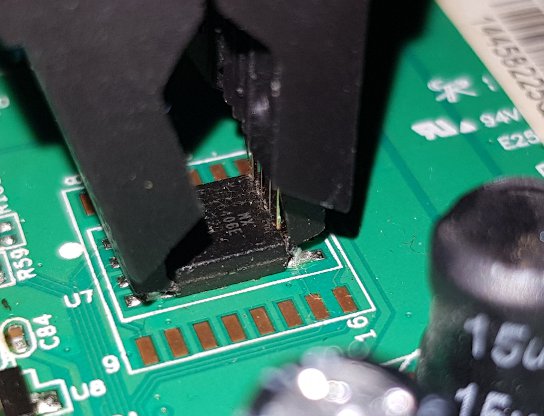
Let's have a look at what are the pins for the flash memory:
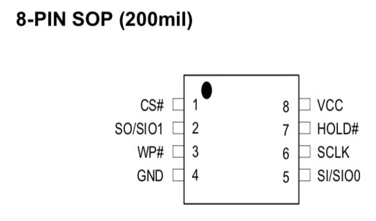
While we quickly learn from reading the pin description that the chip needs to be powered with a 3.3V power supply, we connect everything to the FT232H board, following the instructions from the flashrom wiki. We end up with the following connections to do:
- AD0 (DBUS0) to pin 6
SCLK(for the Serial Clock (SCLK) signal) - AD1 to pin 5
SI(for the Master Out Slave In (MOSI) signal, which is data sent by the computer to the memory) - AD2 to pin 2
SO(for the Master In Slave Out (MISO) signal, for the answers sent back to the computer) - AD3 to pin 1
CS#(for the Slave Select (/SS) or Chip Select (/CS) signal, enabling or disabling the chip when there are several connected on the same communication line. The#or/in the name means it's a function that is active low, that is to say the chip is selected (enabled) when this signal is at the logic level 0 (ground) rather than 1 (VCC))
We need to add a few other connections, for powering the chip:
- GND to pin 4
GND(for the voltage 0 reference) - 3.3V to pin 8
VCC(to power the chip)
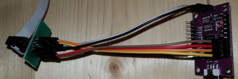
We get the following result:
Programming the chip
The most flexible tool for dealing with memories is flashrom, which can use the FT232H chip as a USB programmer for the Macronix MX25L6406E chip.
Before writing anything, it's better to read, or even just probe the presence of the chip. In this case, it needs the following command:
$ flashrom --programmer ft2232_spi:type=232H --chip MX25L6406E/MX25L6408E
flashrom v1.2 on Darwin 18.7.0 (x86_64)
flashrom is free software, get the source code at https://flashrom.org

Calibrating delay loop... OK.
No EEPROM/flash device found.
Note: flashrom can never write if the flash chip isn't found automatically.
Which is a terrible failure! The chip is unresponsive: "No EEPROM/flash device found."
Conclusion
As you may have guessed, this adventure ends here. I have the impression the router is dead as the memory chip is totally unresponsive. I am not sure how a firmware update could have actually physically damaged the chip to become unresponsive to an external flash programmer.
Other causes for this failure are the following:
- even though the wiring has been checked several times, it is possible there is a faulty contact somewhere;
- there as some other problem somewhere, for example there was some damage to the board when soldering the RS232 connector to the router's printed circuit board (PCB);
- I don't know what I'm doing and I messed up every single step in the way.