Embedded Rust on nRF52840
⚠️ Note: This is the very first article on this blog where GenAI has been used directly. The prompt used was "Here is my article draft, please review and correct it. I am all ears for suggestions and improvements, though, but do not perform the modifications in the text."
Rust and embedded systems
Ever since I've learnt about Rust, about a year before version 1.0, I was sold on the idea. A programming language that offers high-level constructs but without a garbage collector thanks to a very strong-typing system sounds very compelling to me. Technically, this means it has a very low footprint and very few requirements to run, just like C. In other words, you can write code that runs on your computer (using Linux, macOS, or Windows), but also on microcontrollers without relying on any operating system.
After a few years of maturing, programming for microcontrollers moved from theoretically possible to actually practical: the compiler could target the required architecture (usually ARM). Often, that support is not from the manufacturers so all the crates (libraries) for supporting the devices are created/generated and maintained by thrid parties. One notable exception is the cool new Chinese kid in town Espressif with their ESP32 cheap chips. However, when I bought my hardware a few years back, I went another way and gave (much more of) my money to Nordic Semiconductors. The additional components I'll be using in this project are a small, cheap, and questionably accurate DHT22 temperature & humidity sensor as well as a no-name 2.9" black/white/red ePaper display (the link points to a different but suspiciously similar item).
❗️ This article assumes a little bit of familiarity with Rust and its terminology, as well as basics in embedded software. The toolchain setup (installing the thumbv7em-none-eabihf target, the cargo-embed tooling and such) is out of scope of this article.
The project
I bought the hardware with an idea in mind: create a small monitoring system for an indoor plant, checking whether its environment is right, and act on it. For this article, the "act on it" will not be considered even though it's quite interesting which relies on piezoelectric ultrasonic nozzles.
The features we are waiting for are:
- Display of the temperature and humidity on the display.
- Provide a view of historical data.
- Compute statistics.
- Have some nice logging capabilities over the serial port.
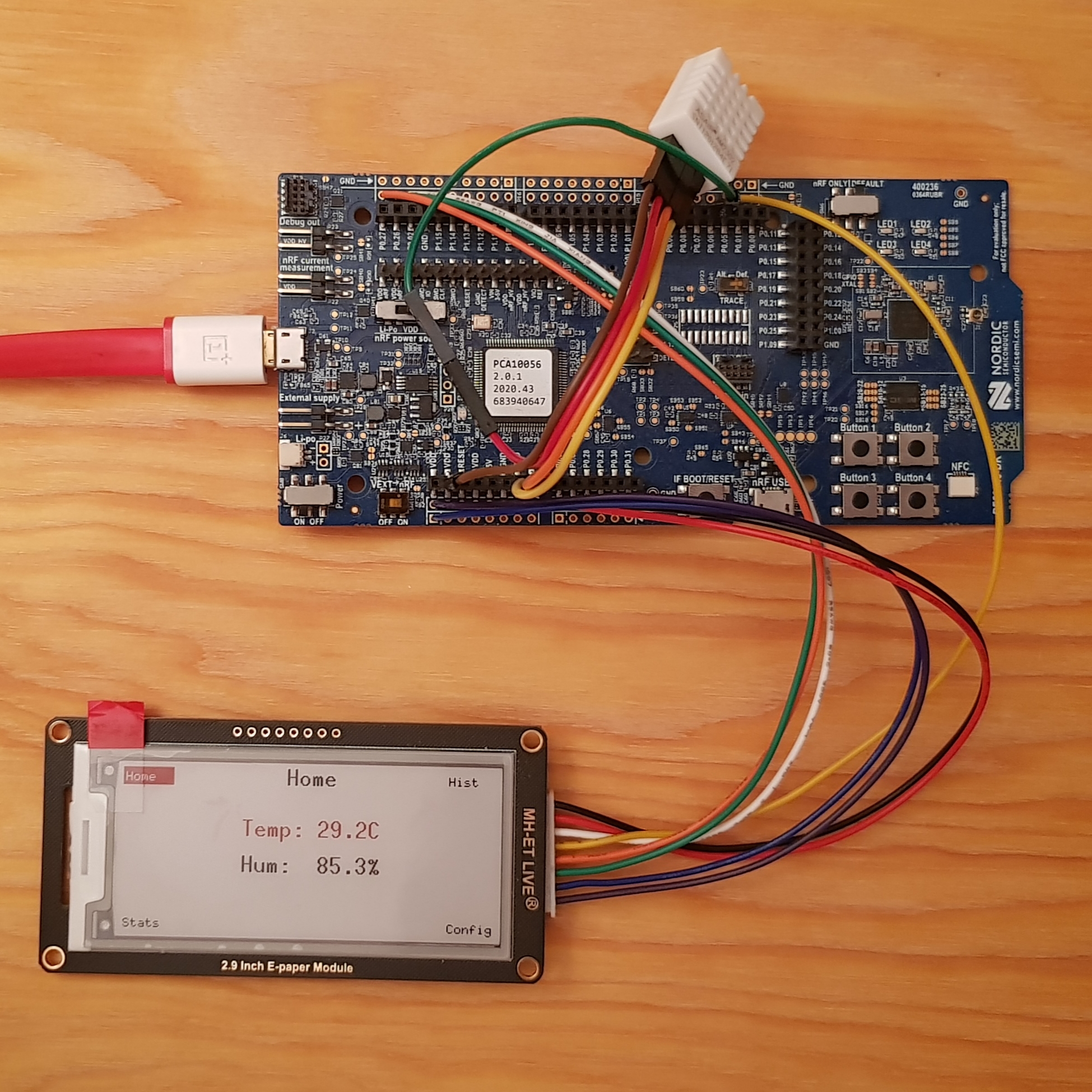
You can see on the display that different pages are available, with their names on each corner (Home, Hist, Stats, and Config). Each page is mapped to one of the four buttons you can see on the bottom right-hand corner of the main board.
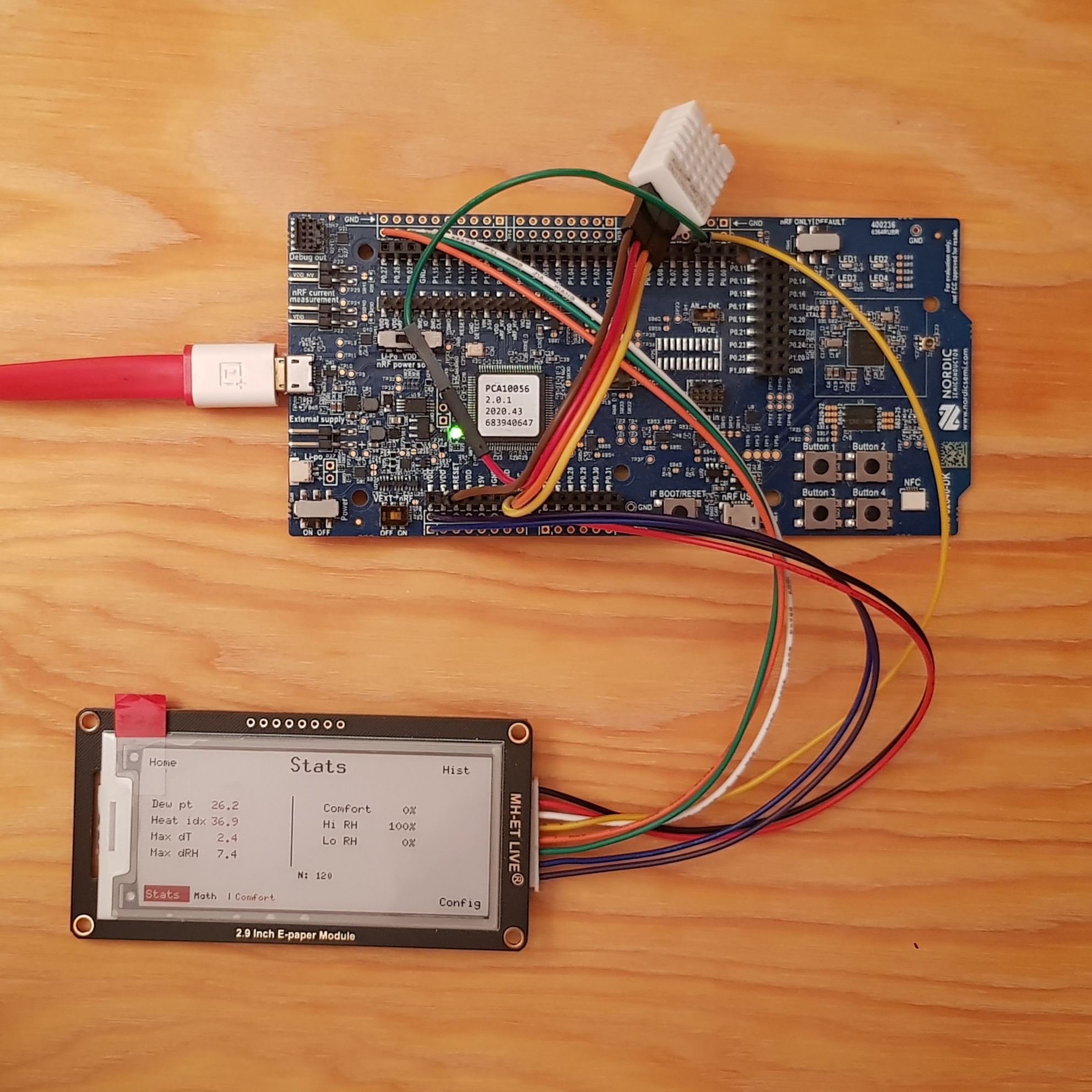
This second photo of the project shows the domain-specific statistics collected: from the temperature and humidity, the app computed the heat index, dew point, etc.
Project setup
One of the first things to do is to create a few mandatory and optional files to tell the Rust compiler to target the device used. In my case, I have both the full-size nRF52840-DK development kit as well as the Adafruit nRF52840 Feather board. I also wanted to have a QEMU target to test without the real hardware, but it's only available in a draft state in the code.
To help myself with the wiring, I also wrote a document to remind me what to connect where. Using colored emojis is very helpful to track the cable colors to the destination pin names. If you see grey rectangles, your system does not the Emoji 12.0 set that came with Unicode 12.0 that came out in 2019.
Display Pin Wiring
Display pin nRF52840-DK pin Notes VCC 🟣 VDD (3.3 V) P1 connector pin 2 — not 5 V GND 🔵 GND P1 connector pin 1 DIN 🟢 P0.26 SPI MOSI CLK 🟠 P0.27 SPI SCK CS 🟡 P0.05 Driven by firmware — do not tie to GND DC ⚪️ P0.02 High = data, low = command RST 🔴 P0.03 Active-low reset BUSY ⚫️ P0.04 Active-low (BUSY_N): LOW = busy, HIGH = ready
Convenience config.toml
# .cargo/config.toml

[build]
target = "thumbv7em-none-eabihf" # Targeting ARM's instruction set

[env]
DEFMT_LOG = "info" # Log-level for defmt
DEFMT_RTT_MODE = "NoBlockSkip" # Drops log messages if the buffer is full rather than blocking

[target.thumbv7em-none-eabihf]
# cortex-m-rt supplies link.x; defmt-rtt supplies defmt.x.
rustflags = ["-C", "link-arg=-Tlink.x", "-C", "link-arg=-Tdefmt.x"]

### Aliases
# Always target the firmware crate explicitly so these work from the
# workspace root without requiring `cd crates/firmware`.
[alias]
# Build, flash, and stream RTT logs on a connected nRF52840-DK.
nrfdk = "embed --manifest-path crates/firmware/Cargo.toml" # default with "--no-default-features --features=board-nrf52840-dk,hardware"
# Build, flash, and stream RTT logs on an Adafruit Feather nRF52840.
feather = "embed --manifest-path crates/firmware/Cargo.toml --no-default-features --features=board-feather-nrf52840,hardware"

# Check for the nRF52840-DK.
check-dk = "check --no-default-features --features hardware,board-nrf52840-dk,environment"
# Check for the Feather nRF52840
check-feather = "check --no-default-features --features hardware,board-feather-nrf52840,environment"
This config file is not strictly mandatory, but it's really helpful to have it anyway: without it, I would need to provide command-line arguments each time I build and flash the firmware.
The aliases defined in the [alias] section are shortcuts for frequent commands to build and flash the firmware or perform a fast type check.
❓ What's that "defmt" thingy in the [env] section?
Good question! It's actually an extremely convenient and efficient way to have a console on the computer. On Arduino, you might have used Serial.println("Hello world! I am %f meters tall", 1.78). This enables the same kind of things using the defmt tool. It is much more efficient than a tool like Serial.println(...) as all the formatting is done on the receiver side. In practice, transforming the floating-point value 1.78 into the characters 1.78 is pretty expensive for a microcontroller, and will possibly turn into a much bigger payload such as 1.7799999999999 which is 15 bytes, instead of the original 4 bytes of the original f32 value.
Root Cargo.toml
I like to split my Rust project into multiple crates, to enforce a strict separation of the different parts of code. For this project, I have the domain crate which is dedicated to handling the application state (which is actually not much work) and the firmware crate that is dealing with all the hardware. As most of the project is about interacting with the hardware, most of the code is in there.
# Cargo.toml

[workspace]
resolver = "2"
members = ["domain", "firmware"]

### Shared embedded profiles
# Optimize for size in every build mode; the nRF52840 has
# 1 MiB flash but keeping the binary small reduces
# flash/erase time during development.
[profile.dev]
opt-level = "s"   # optimize for size
debug = true
codegen-units = 1 # better inlining across crates

[profile.release]
opt-level = "s"
lto = true
codegen-units = 1
strip = false     # keep symbols so defmt can decode log frames
The dev and release compilation profiles are tuned for the embedded use-case. Most notably, the goal is to generate small binaries, hence the opt-level = "s" combined with the codegen-units = 1.
The mysterious .x files
Nothing alien here in the world of microcontrollers. As they are chips which integrate different kind of memories (volatile RAM and Flash storage), we need to tell the flashing tool where and how big they are in order to write the firmware at the correct memory spaces. In practice there are a few more subtleties, but it's enough to get started.
// firmware/memory-nrf52840-dk.x

/* nRF52840-DK development kit
 *
 * Flash: 1024 KiB starting at 0x00000000 (no bootloader reservation).
 * RAM:    256 KiB starting at 0x20000000.
 *
 * cargo-embed flashes directly via SWD/J-Link; no UF2 bootloader is involved.
 */
MEMORY
{
    FLASH : ORIGIN = 0x00000000, LENGTH = 1024K
    RAM   : ORIGIN = 0x20000000, LENGTH = 256K
}
An embedded Rust project usually has just a single memory.x file, but in my case, I want to target different microcontrollers with different configurations. This file, along with a build.rs build script loads and writes the expected memory.x file according to the chosen target.
The firmware's Cargo.toml
This is a hefty one, but actually important. It defines all the dependent crates, but not only. It also defines compile-time features that can be enabled or disabled. All these features are used in this project. Do not worry if it's too much, because it's a file that actually grows little by little, along with your project.
Being a good (and thus, lazy) engineer, I decided to rely heavily on existing crates, instead of reinventing the wheel by reimplementing the same things others did before me. Most notably, here is the list of external crates used:
cortex-mandcortex-m-rt, for having the support of the internal peripherals of the ARM Cortex family.- Embassy, to be able to run Async tasks on microcontrollers. It's a super light executor that is actually faster than an embedded real-time operating system, with less overhead! This includes
embassy-nrffor the specific nRF chip I use. defmt, as explained previously, to get nice logging messages on the connected computer.epd-waveshare, for driving the ePaper display.embedded-graphics, for having primitives to draw shapes and text on a bitmap.
# firmware/Cargo.toml

[package]
name = "firmware"
version = "0.1.0"
edition = "2024"

# ── Features ──────────────────────────────────────────────────────────────────
[features]
default = ["hardware", "board-nrf52840-dk", "environment"]

hardware = [
    "dep:embassy-executor",
    "dep:embassy-futures",
    "dep:embassy-nrf",
    "dep:embassy-sync",
    "dep:embassy-time",
    "dep:embedded-hal-async",
    "dep:defmt-rtt",
    "dep:panic-probe",
    "dep:epd-waveshare",
    "dep:embedded-graphics",
]

environment = []

# Board support packages — select exactly one alongside `hardware`.
board-nrf52840-dk = []
board-feather-nrf52840 = []

# ── Dependencies ──────────────────────────────────────────────────────────────
[dependencies]
domain = { path = "../domain" }
cortex-m = { version = "0.7.6", features = ["critical-section-single-core"] }
cortex-m-rt = "0.7.0"
defmt = "1.0.1"

# ── hardware only ─────────────────────────────────────────────────────────────
embassy-executor = { version = "0.7", optional = true, features = [
    "arch-cortex-m",
    "executor-thread",
    "defmt",
    "task-arena-size-65536", # 64 KiB arena; for history_collection_task + larger history buffer
] }
embassy-futures = { version = "0.1", optional = true }
embassy-nrf = { version = "0.3", optional = true, features = [
    "defmt",
    "nrf52840",
    "time-driver-rtc1", # RTC1 as the Embassy timebase
    "gpiote",           # interrupt-driven GPIO input
] }
embassy-sync = { version = "0.6", optional = true, features = ["defmt"] }
embassy-time = { version = "0.4", optional = true, features = ["defmt"] }
embedded-hal-async = { version = "1.0", optional = true }

defmt-rtt = { version = "1.1.0", optional = true }
panic-probe = { version = "0.3", optional = true, features = ["print-defmt"] }

epd-waveshare = { version = "0.5", optional = true, features = ["graphics"] }
embedded-graphics = { version = "0.7", optional = true }
I admit that there are a lot of required dependencies with specific features. While it's not difficult to identify what's needed and write it manually, I used GenAI to build most of this file. The problem you might encounter when doing this is the use of outdated dependencies, with possible version conflicts. Always check what LLMs are writing out.
The source code
Have you noticed that no code has been written yet? We've only laid the foundations on which to build.
I chose to build the project using a hexagonal architecture, also known as ports-and-adapters.

Image by Cth027, licence CC-BY-SA.
In the context of this project, the application core (which contains the domain-specific application code) is blind to how the data is collected and displayed. The adapters, on the outside of the hexagon, implement how it's done with the real hardware. In other words, the code driving the sensor measurement for temperature and humidity could be replaced by a network request to fetch the data from on online API. It is the same principle for how the data is displayed on-screen.
The type hierarchy makes it pretty clear how the firmware works:
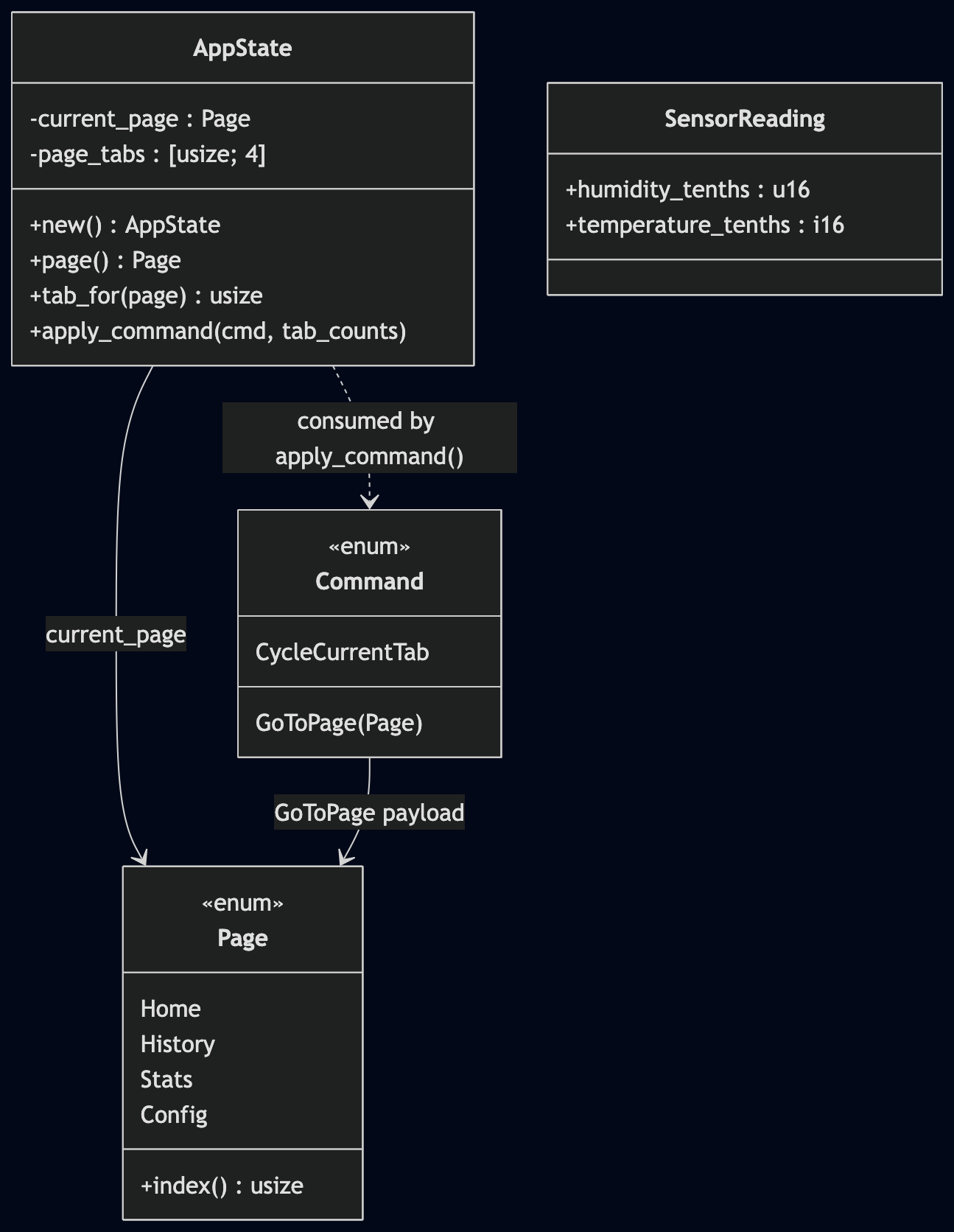
The AppState keeps track of the current page. A page can have multiple tabs, so it is also aware the each page tabs. One remarkable function it exposes is apply_command(...): for better isolation and testability, the actions for changing pages and tabs are carried as Commands. Therefore, when pressing a button, a Command is given to the AppState, which performs the page transition.
The layers in the firmware
The hardware, the core app, the domain-specific renderers.
| Layer | Directory | Description |
|---|---|---|
| User-Interface | renderers/ | Manages how things are displayed on-screen |
| Orchestration | app/ | Domain-specific code, the core application business logic (calls the domain crate) |
| Hardware | hw/ | All the code that is hardware-dependent (outside of the BSP already provided by crates) |
The top layer is really the tip of the iceberg: it is literally the visible part of the system, embodied by pixels on a screen. There is a bit of logic:
- Did the sensor data change enough to pay for the cost of an ePaper screen update?
- How to render the environmental data measured by the sensor?
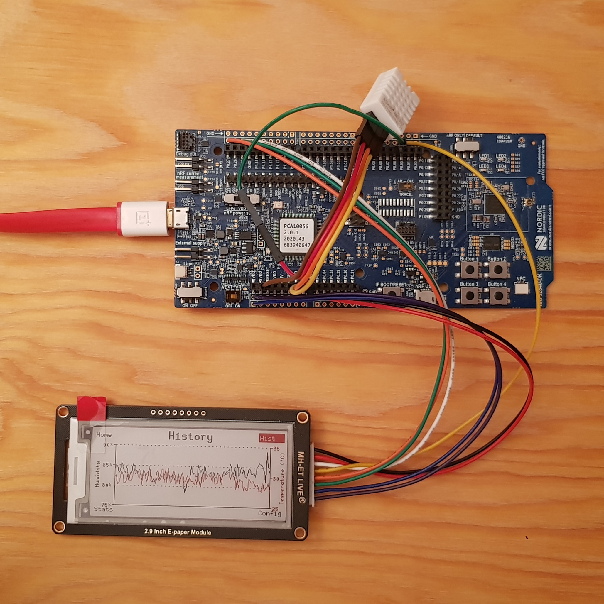
For example, displaying the historical values is only about getting the table of measured values and showing it to the user. By swapping the output device, the same data could be represented differently, achieving the same kind of goal: printing out all the historical values as a spreadsheet on a thermal ticket printer is another way of doing it.
The bottom layer deals with the hardware, talking to the different peripherals (whether they are internal to the microcontroller or external). This layer answers the following questions:
- How do I drive the display?
- How is the board initialized?
- How are the button inputs managed on the different boards?
Note: the latter question is interesting because the Feather board does not have the 4 buttons of the development kit. Therefore, it is not possible to do the mapping "1 button ⇔ 1 page". Instead, it uses a single button, counting the number of presses in a short amount of time to select the correct page, while a long press changes the tab of the current page. This is done in the hw/input/{four,single}_button.rs files, where a dedicated task emits a Command::GoToPage(...) or Command::CycleCurrentTab.
In-between these two layers lies the core of the application. This is the layer that implements the business logic to solve the problem the system has been designed for: measuring environmental data. This is the layer that drives the different tasks of sampling the data, storing it, computing domain-specific statistics, etc.
Inter-Task Communication
Relying on Embassy, which is an async framework, it is rather easy to have a non-blocking execution model: there are multiple tasks running for reacting to button presses, updating the display, performing the measurements, etc.
As you might have noticed, there is a communication problem to solve, which is solved using IPC objects that are sent from one task to another: send messages, do not share data.
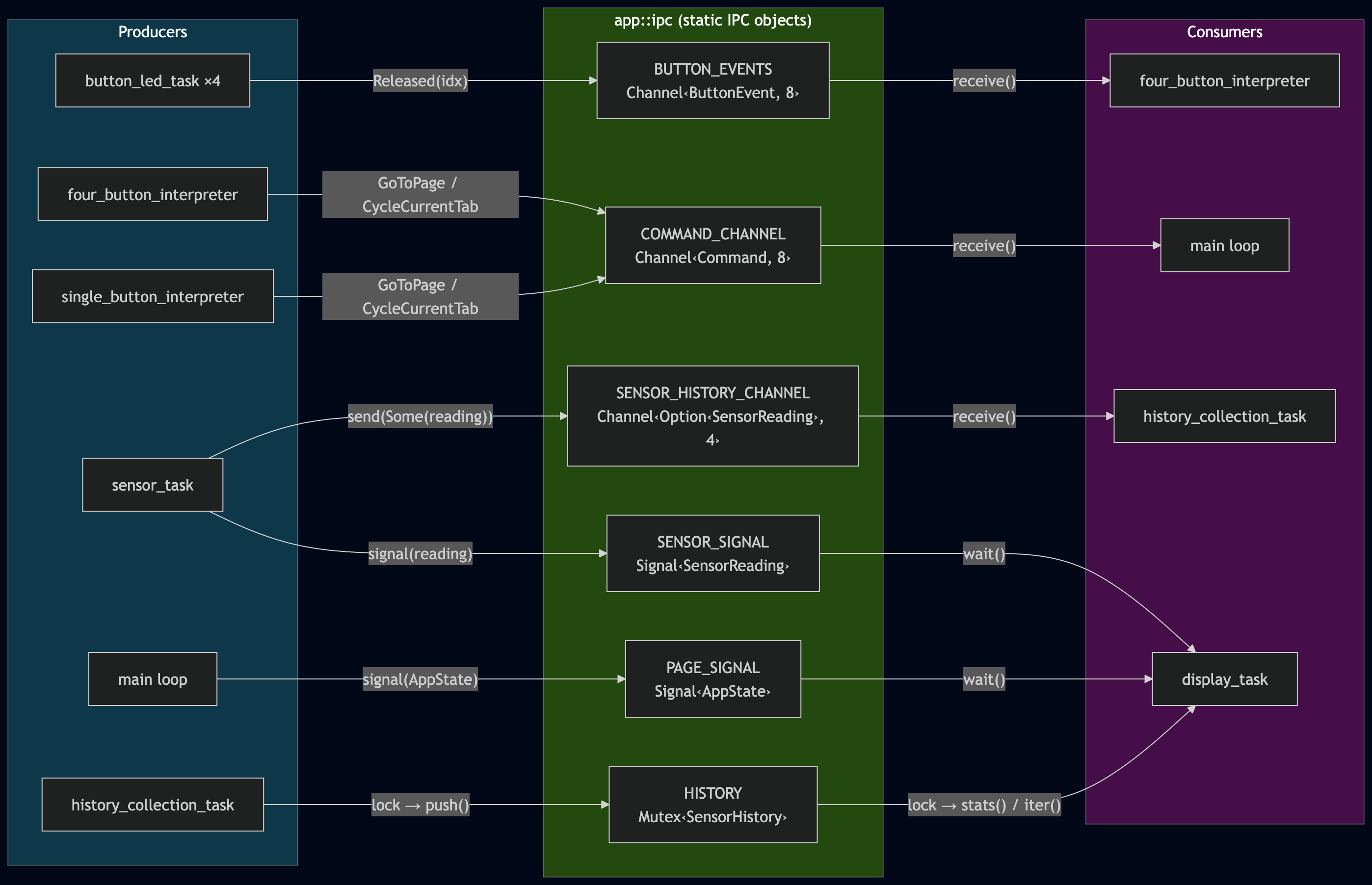
As seen on the diagram, all the 4 button_led_tasks produce a Released object that is put in the BUTTON_EVENTS channel. This channel is read by the four_button_interpreter task. Once this task has decided what the button presses mean, it becomes a producer itself, generating a GoToPage or CycleCurrentTab object that is put in the COMMAND_CHANNEL. The main loop will consume this IPC object, changing the AppState accordingly. Similarly, the main loop will generate an IPC object for the display_task, telling it that new data is available to display on the screen.
ℹ️ Channels or Signals? The two are quite close, and can be easily confused. They work the same, but have slightly different semantics: a Channel will keep all the objects in a queue, for the consumers to eat. A Signal will only keep the most recent one, discarding previous objects if they have not been consumed yet. Two consecutive sensor values must be kept (SENSOR_HISTORY_CHANNEL), while the display commands "Show Home page" followed by "Show History page" should only display the most recently requested page (PAGE_SIGNAL).
Button interpreter
Let's focus a little on the single button interpreter. It is both interesting to explain some effects we have when dealing with physical hardware, what it means to "interpret" the button presses, and view a sequence diagram:
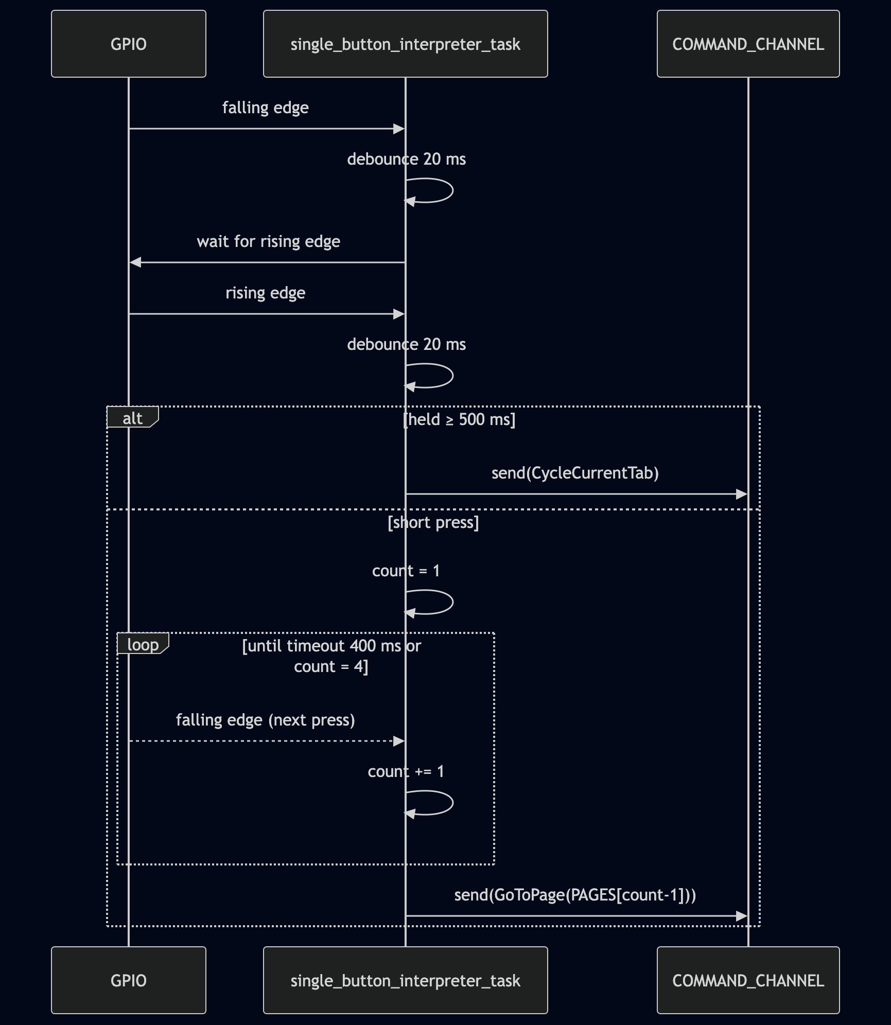
The first step is the debouncing: when pressing physical buttons, the signal is not a clean LOW-to-HIGH rising edge __|⎺⎺. The physical parts are moving, sliding, bouncing against each other, so there is often quite a lot of noise __|⎺⎺|__|⎺|_|⎺⎺⎺ before the signal settles to the logic HIGH value.
There can be hardware approaches to mitigate the problem, charging a capacitor to smoothen the signal, but this is quite uncommon. In practice, a small 20ms timer that is reset when there is some jitter is sufficient. This is what is shown in the sequence diagram, where the GPIO pin connected to the switch detects the rising and falling edges, and sends these events to the interpreter task.
Once the debouncing is done, there are two alternative paths: a long-press triggering a tab change, or a sequence of short presses to encode for the desired page. Once the task has decided what Command to send to the channel, it creates the corresponding IPC object accordingly.
Renderer plugin system
The firmware has been architected in such a way that adding a new sensor domain does not require any change to the application layer. As the nRF chip is Bluetooth-enabled, the board could sense the devices in range. This is a very different kind of environmental sensor, completely unrelated to temperature and humidity.
Each domain (environmental sensing, bluetooth sensing, etc.) registers itself in the renderer registry using a DomainHandlers. Adding a new domain requires:
- Creating a new
renderers/bt/withrender_home(),home_changed_enough(),render_history(), and any domain-specificStatsKindentries. - Adding one
DomainHandlers { … }block to theDOMAINSslice. - Gating everything with
#[cfg(feature = "bt")]to easily enable or disable the feature at compile-time.
ℹ️ Note: While the rendering is indeed completly modular, the statistics accumulation is not yet completly independent. This is planned for future work.
Not refreshing the screen
I have added a full strategy not to refresh the screen. Indeed, as I am using an ePaper display, it consumes energy when changing what is shown. Also, tri-colors displays are notoriously slow, and updating the image takes well over 10 seconds without tweaking it in an undocumented fashion. Therefore, I have quite a significant set of conditions to decide whether the screen needs an update or not:
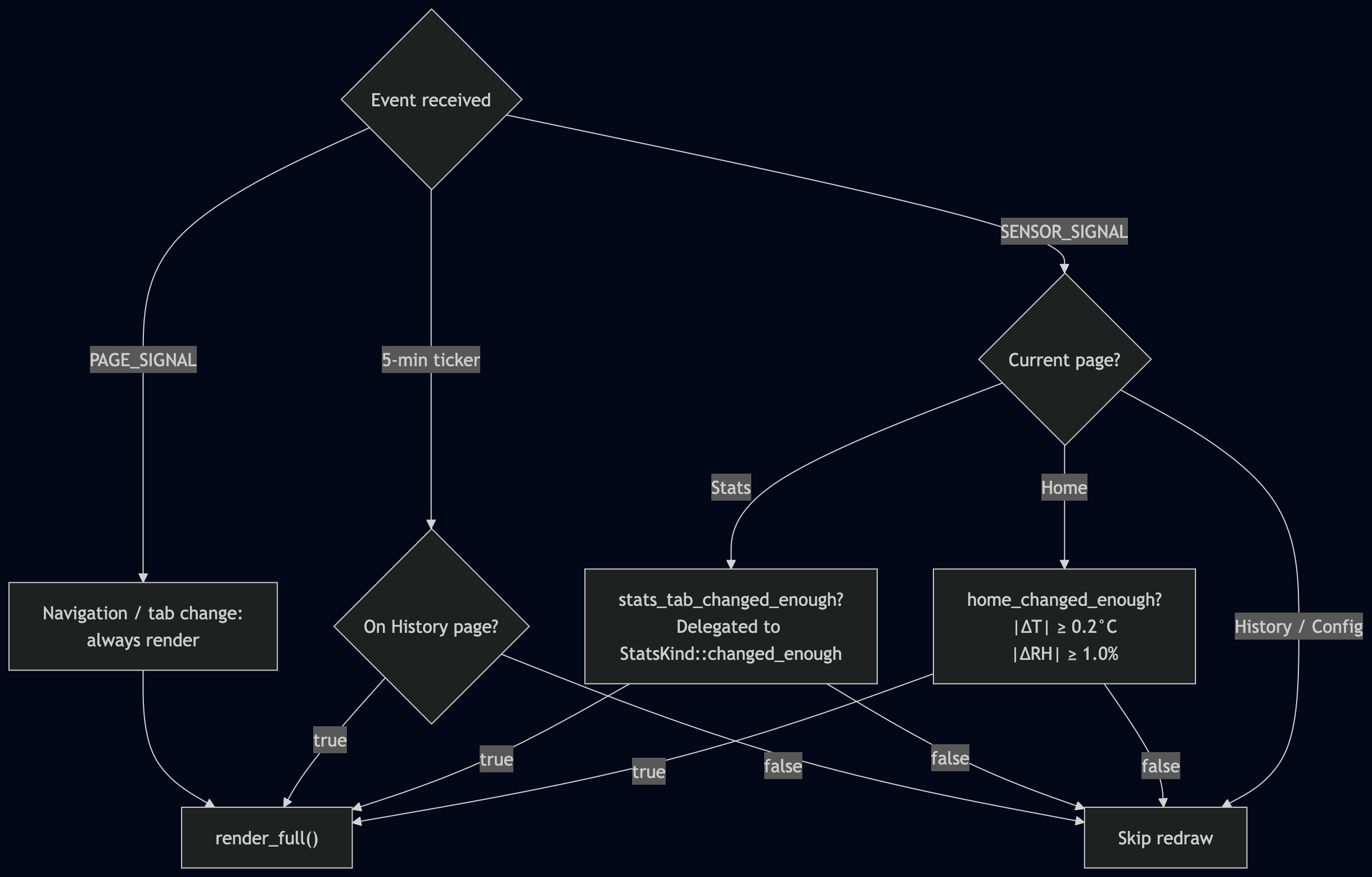
First and foremost, the screen does not need to be updated if nothing happens. In other words, only an event (button press, internal timer, etc.) can trigger a refresh.
- Page changes must always be rendered, otherwise the user-experience is very confusing.
- The Home page displaying the latest sensor readings could skip some renders if the new value is close enough to the displayed value. I have decided that any change smaller than 0.2°C and 1% humidity is negligible.
- The Statistics page follows a similar strategy, where the "changed enough" threshold is part of the domain-specific implementation.
- The History page is not rendered on new sensor data, but it is driven by a five-minute timer instead.
Conclusion
This project is interesting for exploring the capabilities and flexibility of using Rust on bare-metal. The existing crates make it rather easy to use the hardware, from the microcontroller itself to some no-name ePaper displays. The feature gating capabilities using #[cfg(feature = "...")] make it easy to switch boards, or domain-specific sensors, adapting the compiled code to each situation.
This is actually a draft project of mine that I will try to re-use for a more ambitious project. As a draft, it has very few doc-comments, but I tried to have proper .md files for documentation.